Suzuki Samurai Axle Specifications
- Differential Model: Suzuki Samurai 6.9″
- Cover Bolt Quantity: 10
- Carrier Breaks: None
- Carrier/Axle Spline Count: 26
- Inner Axle Spline Count: 22-spline at the differential side (stock)
- Ring Gear Diameter: 6.875”
- Ring Gear Rotation: Standard
- Ring Gear Material: 8620 Steel
- Ring Gear Bolt Quantity: 12
- Ring Gear Bolt Size: 10
- Pinion Diameter: 1.378″
- Pinion Spline: 26
- Axle Tube Diameter: 2.25 inches.
- Joint Type: Birfield-style CV joints.
- Braking System: Solid front disc brakes.
Common Failure Points & Upgrades
Because the stock 22-spline inner shafts are a common weak point when using larger tires, many owners perform the following upgrades:
- 26-Spline Conversion: Using a 26-Spline Side Gear Kit allows the use of stronger Chromoly Front Axles that match the spline count of the rear axle.
- Birfield Upgrades: Kits like the Longfield 33-Spline Kit increase the spline count at the CV joint to 33 for maximum durability in rock crawling.
- Axle Swaps: For extreme builds, owners often swap in Toyota Hilux/4Runner axles or Dana 44 units using conversion kits.
Suzuki Samurai Front Drive Axle Removal & Installation
This guide details the removal and installation of the Suzuki Samurai front drive axle assembly. It is ideal for stock or off-road vehicles requiring axle service, rebuilding, or solid axle swaps. Basic mechanical skills and proper safety precautions are required.
Front Axle Assembly Diagram
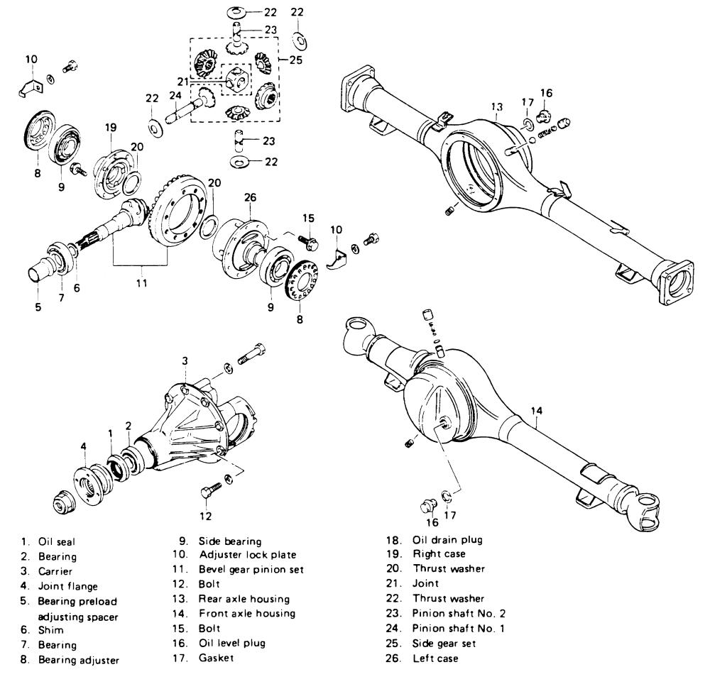
Exploded view of the front and rear axle housing assemblies (click to enlarge)
Front Axle Components
|
|
Front Axle Removal Steps
- Loosen all front wheel lug nuts 1/2 turn. Leave wheels on the axle assembly.
- Apply parking brake, block rear wheels, raise and safely support vehicle on jack stands.
- Support the axle with two hydraulic floor jacks.
- Drain front axle lubricant.
- Detach and plug flexible brake hoses from front calipers.
- If equipped, remove the front stabilizer bar.
- Detach drag rod from right-hand steering knuckle.
- Remove the front driveshaft.
- Remove front shock absorbers.
- Remove front leaf springs.
- Lower the axle assembly carefully, ensuring no cables or wires are in the way.
- Roll the axle assembly out from under the vehicle.
- The axle assembly can now be disassembled if required.
Front Axle Installation Steps
- Assemble front axle components as necessary.
- Roll axle assembly under vehicle and raise slowly on two floor jacks.
- Install front leaf springs, shock absorbers, and driveshaft, aligning driveshaft and differential flange matchmarks.
- Reconnect drag rod to steering knuckle.
- If applicable, install front stabilizer bar.
- Reconnect flexible brake hoses to calipers.
- Bleed brake system.
- Refill front differential with lubricant.
- Lower vehicle and torque front wheel lug nuts to specification.