Visit www.trail-gear.com Today!
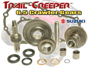
This page shows the installation of Trail Gear 6.5 Crawler Gears for the Samurai transfer case. Not only does it give you great information on how to install the kit to do the work yourself, but gives you a great look inside the case.
6.5 Gear Kit Parts List
-
Gear set
-
Large paper gasket
-
Small paper gasket
-
Counter shaft
-
Two roller bearings
-
Speedo O-Ring
-
Counter shaft shims
-
Output Seals
Tools Required:
- Ratchet, 12mm, 14mm, and 28mm sockets
- Air Wrench
- Needle Nose Pliers
- Hammer
- Grinder
- 3/16 Diameter Pin Punch
- Snap Ring Pliers
- 6mm Allen Wrench
- Gasket Scraper
- Flat Blade Screwdriver
- Adjustable Wrench
- Permatex Ultra Gray Silicon
- Axle Grease
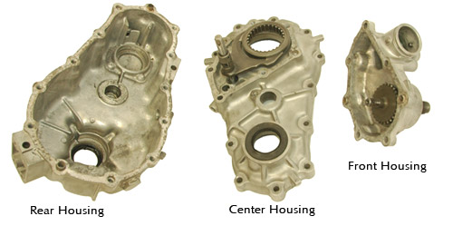
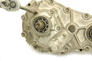
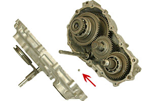
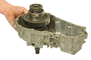
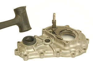
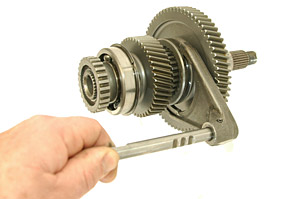
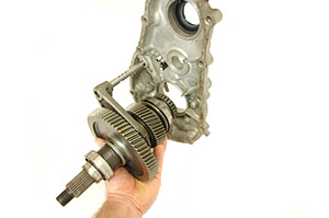
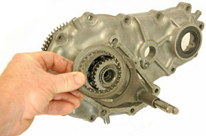
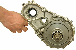
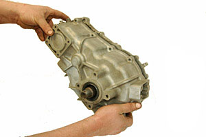
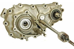
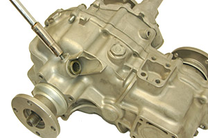
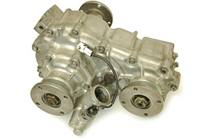
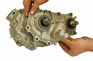
In these instructions we refer to different transfer case housing sections by name. The photo above shows each of the housings and its name.
|
Step 1: Drain oil from transfer case. Remove from truck and remove mounting rails or crossmember from case. |
Step 2: Remove 4wd indicator light using 21 mm wrench. |
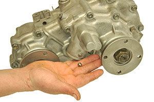
Step 3: Turn transfer case over and collect the 4wd indicator ball as it falls out of the hole for the 4wd indicator. This steel ball is larger then the other two balls removed later. |
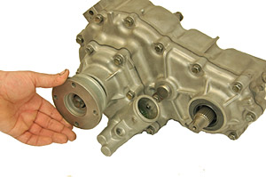
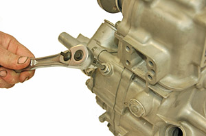
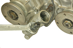
Step 4: Using a 1 1/6″ or 28mm socket remove all three flange nuts and flanges. A bearing puller may be needed to pull flanges off. |
|
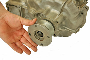
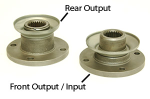
Step 5: Notice that rear output flange is different then the front output and input flanges. |
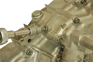
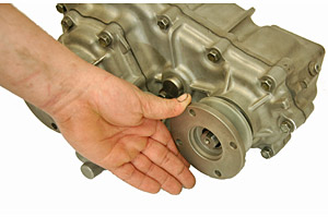
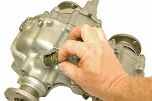
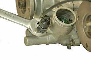
Step 6: On the bottom of the transfer case, remove the detent plug using a 6 mm Allen wrench. |
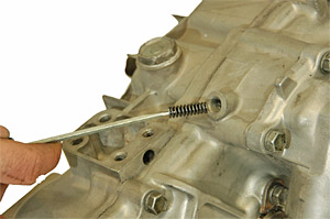
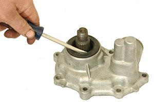
Step 7: Remove detent spring using small screwdriver or punch. Flip case over and remove detent ball. |
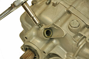
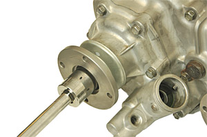
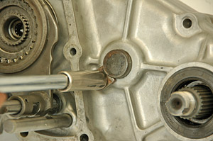
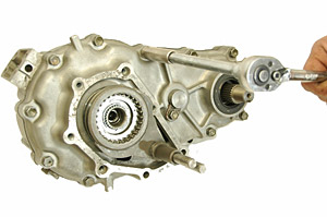
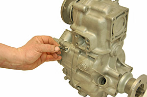
Step 8: Remove speedometer output bolt |
Step 9: Remove speedometer output |
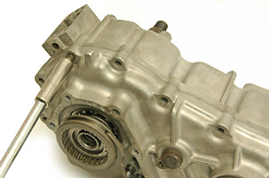
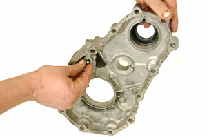
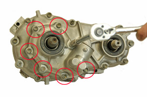
Step 10: Remove 7 bolts holding on front housing. Note the position of each bolt and return each bolt to the same position when reassembling. |
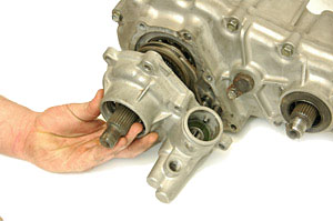
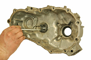
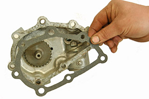
Step 11: Remove front housing |
Step 12: Remove the lock tab and bolt that hold the counter shaft |
Step 13: Remove 11 bolts holding the center and rear housings together. |
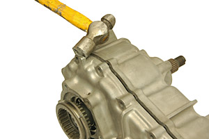
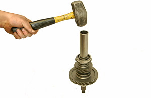
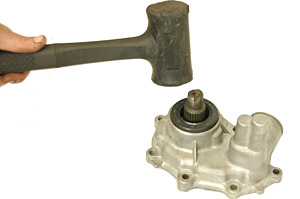
Step 14: Using a small hammer tap the center and rear housing cases apart. |
Step 15: As the cases come apart, be sure to catch the steel ball. This ball will be reinstalled near the end. It may be necessary to tap lightly on the housing to dislodge the ball. |
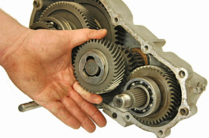
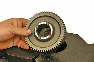
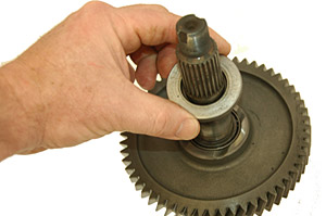
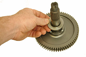
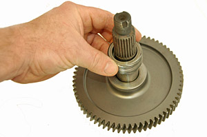
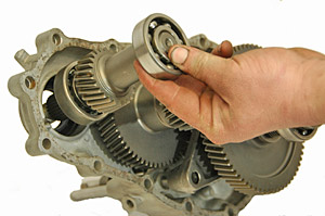
Step 16: Remove the counter shaft gear and shim from the rear housing. |
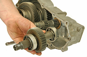
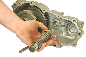
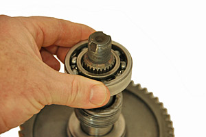
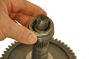
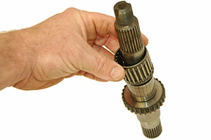
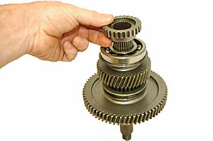
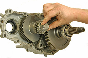
Step 17: Remove the input gear and bearing assembly. |
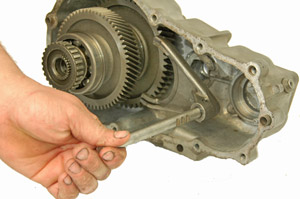
Step 18: Remove the counter shaft, bearings and shim. |
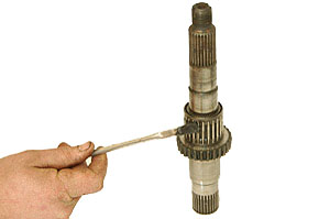
Step 19: Remove shift fork assembly as shown. |
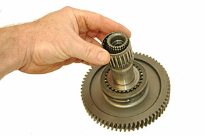
Step 20: Remove the output gear assembly from the rear housing. Hold rear housing and press down on housing to dislodge output. It may be necessary to lift and drop the housing on a flat surface to get it apart. |
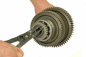
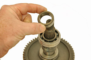
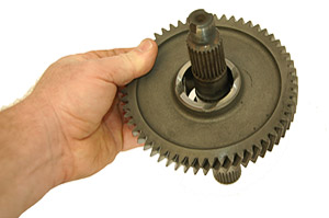
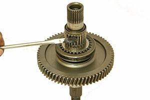
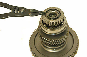
Step 21: Remove the snap ring from the end of the output gear. |
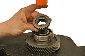
Step 22: Remove the gear as shown. |
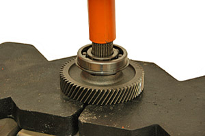
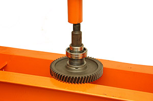
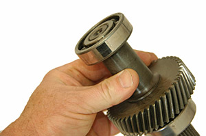
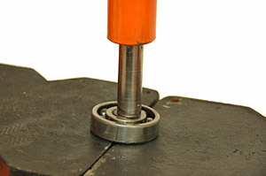
Step 23: Using a press, press the output gear through the bearing as shown. |
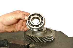
Step 24: Remove the output bearing. |
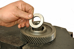
Step 25: Remove spacer from the low output gear. |
Step 25: Remove high speed output gear. |
Step 27: Remove needle bearing assembly from shaft. |
Step 28: Remove shift collar. |
Step 29: Turn gear assembly upside down and press output shaft through low speed gear. |
Step 30: Remove bearing keeper. |
Step 31: Remove bearing. |
Step 32: Remove drive gear |
Step 33: Remove shim |
Step 34: Remove low speed gear |
Step 35: Remove cage bearing. Clean cage bearings, shafts and housings. |
Step 36: Reinstall cage bearing on output shaft. |
Step 37: Install new low speed gear on to output shaft. |
Step 38: Reinstall spacer. |
Step 39: Reinstall drive gear. |
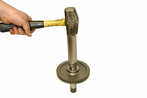
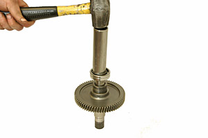
Step 40: Using a piece of tubing, press or hammer drive gear down on to shaft. |
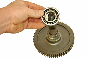
Step 41: Reinstall bearing on to shaft. |
Step 42: Press bearing in to place. |
Step 43: Reinstall collar. |
Step 44: Press collar in to place. |
Step 45: Flip over output shaft to assemble other side. Slide shift collar in to place. |
Step 46: Reinstall bearing on to shaft. |
Step 47: Apply grease to bearing. |
Step 48: Install new high speed output gear. |
Step 49: Reinstall shim |
Step 50: Reinstall bearing and press in to place. |
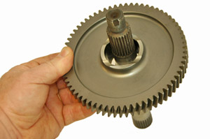
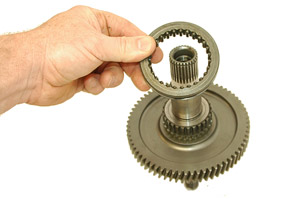
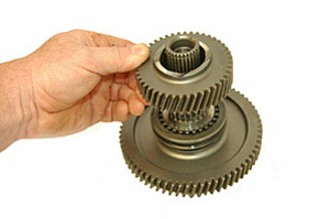
Step 51: Install gear as shown. |
 Step 52: Reinstall snap ring. |
Step 53: Using a press, remove the bearings from both ends of the input shaft. |
Step 54: A socket that is smaller then the shaft size works well for pressing out the bearings. We suggest a 14mm, 3/8″ drive socket. |
Step 55: Once the first bearing is removed, flip the gear over to press off the second bearing. |
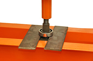
Step 56: Strips of 1/4″ plate steel work well for getting in between the input gear and bearing on the drive flange end of the shaft. |
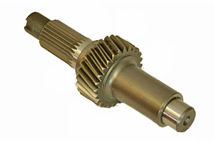
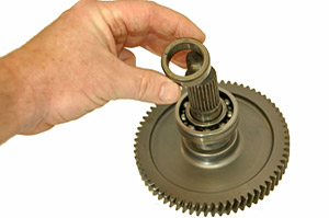
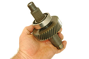
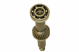
Step 57: Discard original input shaft. The new input shaft is shown above. |
Step 58: Reinstall bearing on end of shaft as shown. |
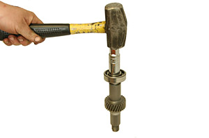
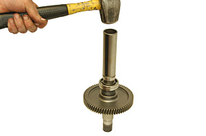
Step 59: Using a socket and press or hammer, press bearing in to place. |
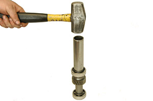
Step 60: Install bearing on the other side of input shaft and press bearing in to place. |
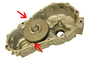
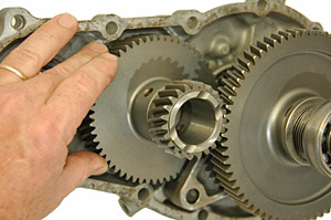
Step 61: Temporarily install counter shaft, new counter shaft gear and bearings. Look for gear rubbing at the points above. |
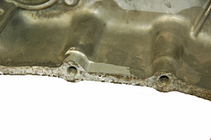
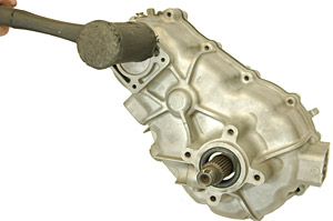
Step 62: Grind as needed with a Dremel rotary tool to prevent gear interference with the case. Remove counter shaft and gear when grinding is complete. |
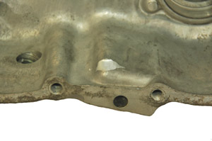
Step 63: Both sides of the case may need to be clearanced. Spin gear in place to ensure that it des not grind on the case. |
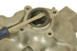
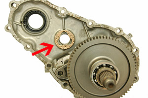
Step 64: Remove and inspect the shifter seat. |
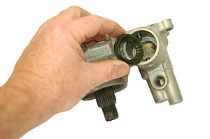
Step 65: Check to see that there are no cracks or missing material. If there is any sign of wear, replace the seat with a new one. |
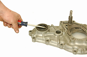
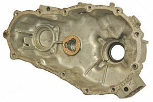
Step 66: Remove old rear output seal from the rear housing. |
Step 67: Install new rear seal provided with kit. |
Step 68: Remove old front input seal. |
Step 69: Install new front input seal provided with kit. |
Step 70: Remove old front output seal. |
Step 71: Install new front output seal provided in kit. |
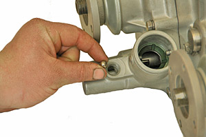
Step 72: Install steel ball in center housing as shown above. This is ball that was removed in step #15 |
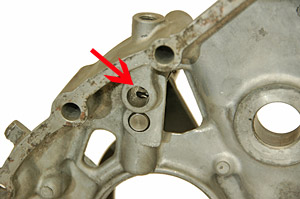
Step 73: Adjust shift rail, until ball drops in to the slot and nearly out of view as shown. |
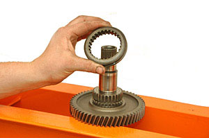
Step 74: Slide high/low shift rail in on to output gear assembly. |
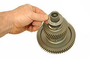
Step 75: Slide gear assembly in to center housing. |
Step 76: Install front output shift collar on to shift fork |
|
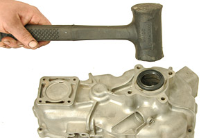
Step 77: Tap output assembly in to place using a rubber hammer. |
Step 78: Apply grease to counter shaft shim face on center housing. |
Step 79: Apply new shim provided in kit. Note position of the tab in shim. Make sure tab fits in to the notch in the housing. |
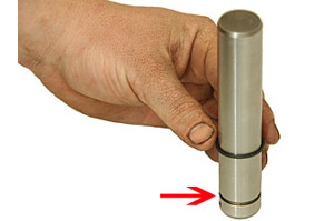
Step 80: Replace rubber seal on counter shaft. Rubber should rest in the groove cut in to shaft. |
Step 81: Place counter shaft gear on to shim. |
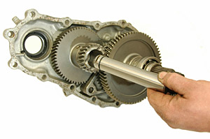
Step 82: Slide counter shaft through counter shaft gear and shim. |

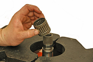
Step 83: Apply grease to new counter shaft bearing provided and slide into center of counter shaft gear. |
Step 84: Slide bearing spacer in to place as shown. |
Step 85: Apply grease to second new counter shaft bearing provided and slide into center of counter shaft gear. |
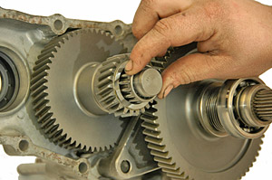
Step 86: Slide input gear assembly on to place. |
Step 87: Apply grease in to counter shaft hole in rear housing. |
Step 88: Place new counter shaft shim over hole in rear housing. Note position of the tab on shim. Make sure tab fits in to the notch in the housing. |
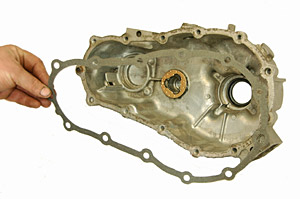
Step 89: Apply Permitex Ultra Grey silicon to both sides of gasket and lay gasket over rear housing. |
Step 90: Slide rear housing on top of center housing section. Make sure not to pinch or damage gasket. Counter shaft must fit in to center of shim. |
Step 91: Tap center and rear housings together with rubber hammer. |
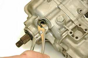
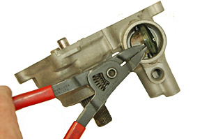
Step 92: Turn counter shaft with pliers so that lock tab slot lines up with tab hole. Install lock tab and bolt. |
Step 93: Install 11 bolts that hold the center and rear sections together. Be sure to install bolts in the same places as they were removed from. Not all the bolts are the same size. |
Step 94: Apply ultra gray silicon to both sides of front housing gasket. Place gasket over front housing. |
|
Step 95: Install front housing section on to center housing. |
Step 96: Install 7 bolts holding front housing. Be sure to install bolts in the same places as they were removed from. Not all the bolts are the same size. |
Step 97: Install front output flange. Install flange nut and restake nut in to position. |
Step 98: Install input flange. Install flange nut and restake nut in to position. |
Step 99: Install rear output flange. Note that the rear output flange is the tall flange and is different then the other two flanges. Install flange nut and restake nut in to position. |
Step 100: Reinstall steel ball in bottom of case. |
|
Step 101: Install spring in to bottom of case. |
Step 102: Install detent plug in to bottom of case. |
Step 103: Install speedometer drive unit. |
Step 104: Install speedometer drive bolt. |
Step 105: Install 4wd indicator ball (removed in step #3) as shown. |
Step 106: Install 4wd indicator switch as shown. |
After installing transfer case, use the rear fill plug and fill transfer case with 80/90W GL5 gear oil. Once oil starts leaking out of the fill hole, the transfer case case is full. Transfer case oil should be replaced after 1,000 miles, then at every 30,000 miles thereafter. Conventional or synthetic oil may be used.

These instructions are designed as a general installation guide. Installation of Trail-Gear Products requires specialized skills such as metal fabrication, welding and mechanical trouble shooting. If you have any questions or are unsure about how to proceed, please contact our shop at 559-252-4950 or seek help from a competent fabricator. Using fabrication tools such as welders, torches and grinders can cause serious bodily harm and death. Please operate equipment carefully and observe proper safely procedures.
Rock crawling and off-road driving are inherently dangerous activities. Some modifications will adversely affect the on-road handling characteristics of your vehicle. All products sold by Trail-Gear Inc are sold for off road use only. Any other use or application is the responsibility of the purchaser and/or user. Some modifications and installation of certain aftermarket parts may under certain circumstances void your original dealer warrantee. Modification of your vehicle may create dangerous conditions which could cause roll-overs resulting in serious bodily injury or death. Buyers and users of these products hereby expressly assume all risks associated with any such modifications and use.