|
1.6L 8-Valve Timing Specs |
|
| Spark Plug Gap | 0.030 |
| Ignition Timing (deg) Manual Transmission | 8 Degrees Before |
| Ignition Timing (deg) Automatic Transmission | 8 Degrees Before |
NOTE: Do not rotate the crankshaft counterclockwise or attempt to rotate the crankshaft by turning the camshaft sprocket.
- Remove the timing belt cover.
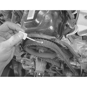
- If the timing belt is not already marked with a directional arrow, use white paint, a grease pencil or correction fluid to do so.
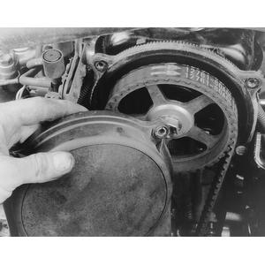
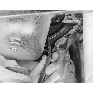
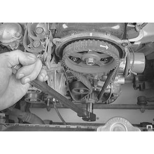
- Disconnect one end of the tensioner spring. Loosen the timing belt tensioner bolt and stud, then, using your finger, press the tensioner plate up and remove the timing belt from the crankshaft and camshaft sprockets. Remove the outer timing belt cover from the engine . . .
 |
. . . however, if not already marked, use paint or correction fluid to indicate the direction of travel
 |
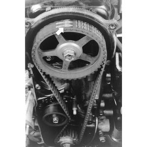
If necessary, when removing the tensioner spring (A), loosen the spring anchor bolt (B)
 |
Loosen the tension plate, spring bolt and stud nut to remove the plate from the engine . . .
 |
. . . then loosen the tension adjuster pulley center bolt for adjuster removal
 |
- Remove the timing belt tensioner, tensioner plate and spring from the engine.
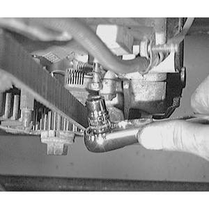
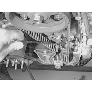
- Insert a metal rod through the hole in the camshaft to lock the camshaft from rotating. Loosen the camshaft sprocket retaining bolt, then pull the camshaft sprocket off of the end of the camshaft.
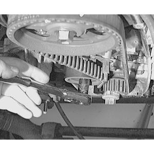
- Remove the crankshaft timing belt sprocket by loosening the center bolt, while preventing the crankshaft from rotating. To hold the crankshaft from turning, you can use Suzuki Tool 09927–56010 (or equivalent), or a large prybar inserted in the transmission housing slot and the flywheel teeth. Pull the sprocket off of the end of the crankshaft. Be sure to retain the crankshaft sprocket key and belt guide for assembly.
- If necessary, remove the timing belt inside cover from the cylinder head. Remove the timing belt from crankshaft and camshaft sprockets
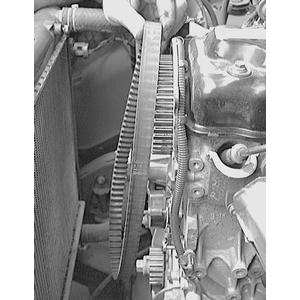
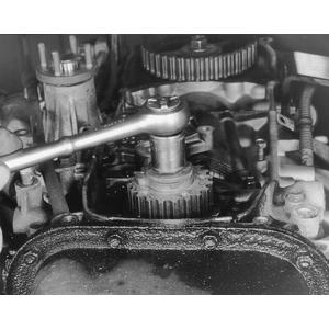
Fig. 1: Use a metal rod (2) inserted through the camshaft hole to secure it from rotating . . . 
Fig. 2: . . . then remove the camshaft sprocket retaining bolt and the sprocket from the end of the camshaft 
 |
. . . while you loosen the crankshaft sprocket retaining bolt
 |
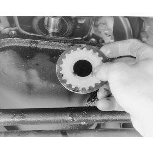
Slide the sprocket off of the end of the crankshaft . . .
 |
. . . and be sure to retain the timing belt guide for reassembly
 |
To install:
- If necessary, install the timing belt inside cover.
- Slide the timing belt guide on the crankshaft so that the concave side faces the oil pump, then install the sprocket key in the groove in the crankshaft.
- Slide the pulley onto the crankshaft, and install the center retaining bolt. Tighten the center bolt to 48–54 ft. lbs. (65–75 Nm) for 1986–88 1.3L engines, to 76–83 ft. lbs. (105–115 Nm) for 1989–95 1.3L engines, or to 58–65 ft. lbs. (80–90 Nm) for 1.6L engines. To hold the crankshaft from turning, you can use Suzuki Tool 09927–56010 (or equivalent), or a large prybar inserted in the transmission housing slot and the flywheel teeth.
- Install the timing belt camshaft sprocket, ensuring that the slot in the sprocket engages the camshaft (pulley) pin; this ensures that the sprocket is properly positioned on the end of the camshaft. Secure the camshaft with the metal rod used during removal, then tighten the sprocket bolt to 41–46 ft. lbs. (56–64 Nm).
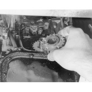
- Assemble the timing belt tensioner plate and the tensioner, making sure that the lug of the tensioner plate engages the tensioner.
Fig. 3: Assemble the tensioner (2) and the plate (1) so that the lug (3) engages the hole (4) in the tensioner 
- Install the timing belt tensioner, tensioner plate and spring on the engine. Tighten the mounting bolt and stud only finger-tight at this time. Ensure that when the tensioner is moved in a counterclockwise direction, the tensioner moves in the same direction. If the tensioner does not move, remove it and the tensioner plate to reassemble them properly.
- Loosen all rocker arm valve lash locknuts and adjusting screws. This will permit movement of the camshaft without any rocker arm associated drag, which is essential for proper timing belt tensioning. If the camshaft does not rotate freely (free of rocker arm drag), the belt will not be properly tensioned.
- Rotate the camshaft sprocket clockwise until the timing mark on the sprocket and the V mark on the timing belt inside cover are aligned.
- Using a 17mm wrench, or socket and breaker bar, on the crankshaft sprocket center bolt, turn the crankshaft clockwise until the punch mark on the sprocket is aligned with the arrow mark on the oil pump.
Fig. 4: When installing the crankshaft sprocket (pulley), ensure that the concave side of the timing belt guide is facing the engine 
Fig. 5: Before installing the timing belt, position the camshaft sprocket (1) so that the timing mark on the sprocket (2) is aligned with the notch (3) on the inside timing belt cover (4) . . .
Fig. 6: . . . and ensure that the crankshaft sprocket (1) timing mark (2) is aligned with the mark on the oil pump (3) 
Fig. 7: Install the timing belt on the sprockets so that there is no slack in the drive side of the belt (1), then install the tensioning assembly 
(Click To Enlarge)
 |
- With the camshaft and crankshaft marks properly aligned, push the tensioner up with your finger and install the timing belt on the two sprockets, ensuring that the drive side of the belt is free of all slack. Release your finger from the tensioner. Be sure to install the timing belt so that the directional arrow is pointing in the appropriate direction.NOTE: In this position, the No. 4 cylinder is at Top Dead Center (TDC) on the compression stroke.
- Rotate the crankshaft clockwise two full revolutions, then tighten the tensioner stud to 18–21 ft. lbs. (24–30 Nm) for 1986–88 models, or to 80–106 inch lbs. (9–12 Nm) for 1989–95 models. Then, tighten the tensioner bolt to 18–21 ft. lbs. (24–30 Nm).
- Ensure that all four timing marks are still aligned as before; if they are not, remove the timing belt, and install and tension it again.
- Install the timing belt cover and all related components.
1.6L 16-Valve Engine
The 1.6L 16-valve engine is known as an interference motor, because it is fabricated with such close tolerances between the pistons and valves that, if the timing belt is incorrectly positioned, jumps teeth on one of the sprockets or breaks, the valve and pistons will come into contact. This can cause severe internal engine damage. Therefore, it is vitally important to inspect and replace the timing belt as indicated in the maintenance intervals charts in Section 1.
NOTE: Do not rotate the crankshaft counterclockwise or attempt to rotate the crankshaft by turning the camshaft sprocket.
Fig. 8: Prior to timing belt removal, rotate the crankshaft clockwise until the camshaft and crankshaft sprocket marks are aligned with the marks on the engine . . . |
Fig. 9: . . . then remove the timing belt and tensioner assembly from the engine |
Fig. 10: Once the timing belt is removed, do not rotate the camshaft or crankshaft further than their acceptable range, as indicated
(Click To Enlarge) |
- Remove the timing belt cover.
- If the timing belt is not already marked with a directional arrow, use white paint, a grease pencil or correction fluid to do so.
- Rotate the crankshaft clockwise until the timing mark on the camshaft sprocket and the V mark on the timing belt inside cover are aligned, and the punch mark on the crankshaft sprocket is aligned with the mark on the engine. WARNING
Do not rotate the crankshaft or camshaft once the timing belt is removed, because the valves and pistons can come into contact, which may cause internal engine damage. - Disconnect one end of the tensioner spring. Loosen the timing belt tensioner bolt and stud, then, using your finger, press the tensioner plate up and remove the timing belt from the crankshaft and camshaft sprockets.
- Remove the timing belt tensioner, tensioner plate and spring from the engine.
- Install Suzuki Tool 09917–68220, or equivalent, onto the camshaft sprocket to hold the camshaft from rotating. Loosen the camshaft sprocket retaining bolt, then pull the camshaft sprocket off of the end of the camshaft.
Fig. 11: Use a spanner tool (A) to hold the camshaft sprocket steady while loosening the retaining bolt (a) 
- Remove the crankshaft timing belt sprocket by loosening the center bolt, while preventing the crankshaft from rotating. To hold the crankshaft from turning, you can use Suzuki Tool 09927–56010 (or equivalent), or a large prybar inserted in the transmission housing slot and the flywheel teeth. Pull the sprocket off of the end of the crankshaft. Be sure to retain the crankshaft sprocket key and belt guide for assembly.
- If necessary, remove the timing belt inside cover from the cylinder head.To install:
- If necessary, install the timing belt inside cover.
- Slide the timing belt guide on the crankshaft so that the concave side faces the oil pump, then install the sprocket key in the groove in the crankshaft.
- Slide the pulley onto the crankshaft, and install the center retaining bolt. Tighten the center bolt to 80 ft. lbs. (110 Nm). To hold the crankshaft from turning, you can use Suzuki Tool 09927–56010 (or equivalent), or a large prybar inserted in the transmission housing slot and the flywheel teeth.
- Install the timing belt camshaft sprocket, ensuring that the slot in the sprocket engages the camshaft (pulley) pin; this ensures that the sprocket is properly positioned on the end of the camshaft. Secure the camshaft with the holding tool used during removal, then tighten the sprocket bolt to 44 ft. lbs. (60 Nm).
- Assemble the timing belt tensioner plate and the tensioner, making sure that the lug of the tensioner plate engages the tensioner.
Fig. 12: After installing the tensioner and plate, ensure that the plate moves when the tensioner is rotated in a counterclockwise direction 
- Install the timing belt tensioner, tensioner plate and spring on the engine. Tighten the mounting bolt and stud only finger-tight at this time. Ensure that when the tensioner is moved in a counterclockwise direction, the tensioner moves in the same direction. If the tensioner does not move, remove it and the tensioner plate to reassemble them properly.
- Loosen all rocker arm valve lash locknuts and adjusting screws. This will permit movement of the camshaft without any rocker arm associated drag, which is essential for proper timing belt tensioning. If the camshaft does not rotate freely (free of rocker arm drag), the belt will not be properly tensioned.
- Rotate the camshaft sprocket clockwise until the timing mark on the sprocket and the V mark on the timing belt inside cover are aligned.
Fig. 13: Before installing the timing belt, ensure that the camshaft sprocket mark is aligned with the notch in the inside timing belt cover . . . 
Fig. 14: . . . and be sure that the crankshaft sprocket marks are also aligned 
- Using a wrench, or socket and breaker bar, on the crankshaft sprocket center bolt, turn the crankshaft clockwise until the punch mark on the sprocket is aligned with the arrow mark on the oil pump.
- With the camshaft and crankshaft marks properly aligned, push the tensioner up with your finger and install the timing belt on the two sprockets, ensuring that the drive side of the belt is free of all slack. Release your finger from the tensioner. Be sure to install the timing belt so that the directional arrow is pointing in the appropriate direction.NOTE: In this position, the No. 4 cylinder is at Top Dead Center (TDC) on the compression stroke.
- Rotate the crankshaft clockwise two full revolutions, then tighten the tensioner stud to 97 inch lbs. (11 Nm). Then, tighten the tensioner bolt to 18 ft. lbs. (24 Nm).
- Ensure that all four timing marks are still aligned as before; if they are not, remove the timing belt, and install and tension it again.
- Install the timing belt cover and all related components.